The Hardware Design of ArrayBot
A tutorial on building the ArrayBot.
ArrayBot is a 16×16 array of vertically actuated pillars, each equipped with tactile sensors, published at ICRA 2024.
For a visual demonstration of ArrayBot’s capabilities, you can view the following video:
I designed all the hardware for ArrayBot myself. While I’m happy to share the details, its complex structure makes it pretty tough to build. As you can see in the picture below, even with a bunch of people helping, it still took me more than 24 hours straight to put it all together.
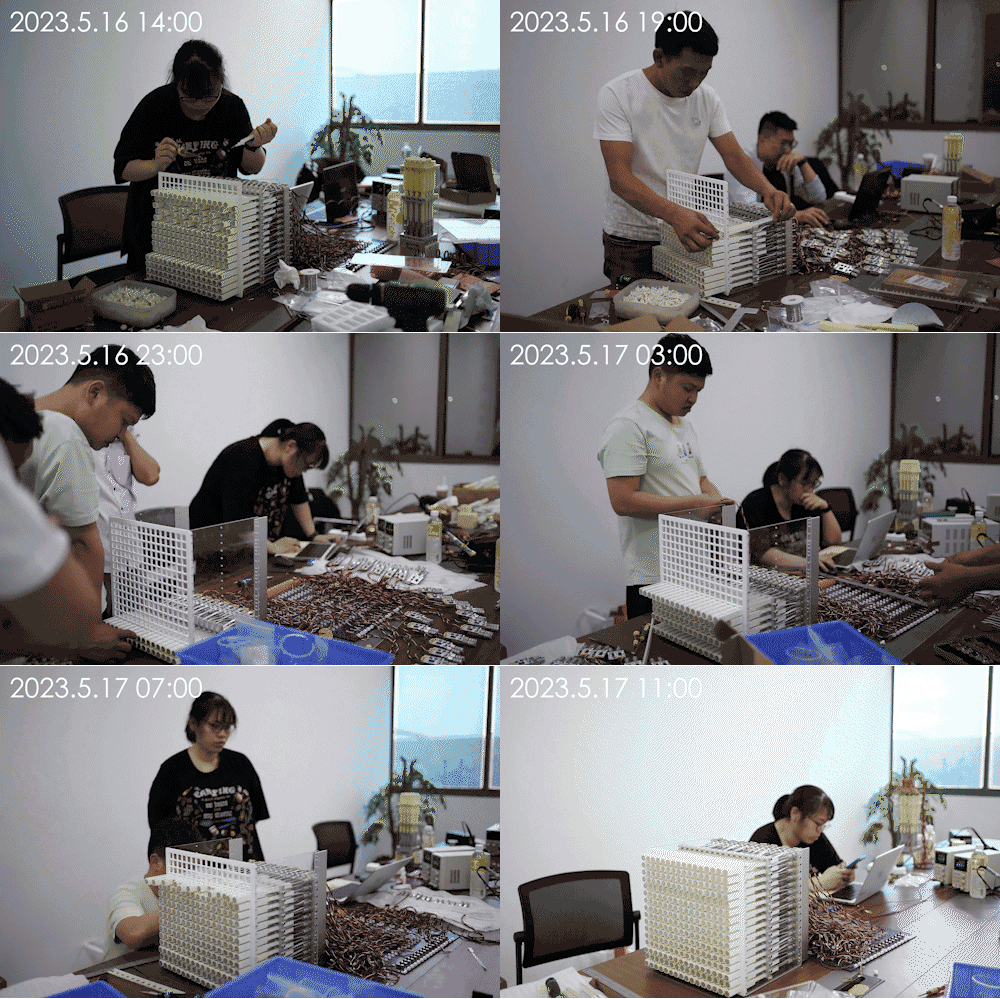
Detailed Hardware Demo
I built a UI to visualize the pillar height and tactile information. The video below shows me testing a smaller version of ArrayBot, the 4x4 model.
In the first video, you can see that when I tap on the ArrayBot’s surface, the pressure grid in the UI changes from dark to light. Dark represents higher pressure, while light means lower pressure. Since the FSR tactile sensor isn’t super precise, we ended up binarizing its data for the RL policy.
In the second video, I send a command to lift all the pillars. The height grid in the UI also shifts from dark to light — dark shows lower heights, and light shows higher heights.
Key Highlights of the Hardware design
In this post, I’ll cover some key points about the hardware design. If you need more help, just let me know! You can leave a comment below or email me directly—I’m always happy to help you build your own ArrayBot.
The Atom Unit of ArrayBot
The hardware of ArrayBot can be perceived as a 16 × 16 array of vertically sliding atom units.
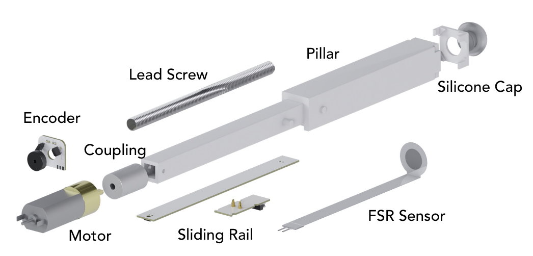
Each atom unit is composed of the following components:
| Component | Description | Link |
|---|---|---|
| DC Motor | Provides motion for the unit. | Chihai Motor, 050, DC 12V, 800 rpm (Reduction ratio 20:1) |
| Encoder Board | Tracks the motor’s position and movement. | Custom design |
| Sliding Rail | Ensures smooth motion while maintaining undisturbed FSR signal transmission. | Custom design |
| Coupling | Connects the motor to the lead screw. | Parallel Line Coupling D12L18.5, 3mm to 5mm |
| Lead Screw with Screw Nut | Converts rotational motion into linear motion. | T5*4 Lead Screw, Pitch 1mm, Length 100mm with Square Screw Nut |
| Pillar | Provides linear motion (dimensions: 16mm × 16mm × 200mm). | Custom design |
| Force Sensing Resistor (FSR) | A Low-cost tactile sensor for pressure detection. | RXD1016, Male terminal, Range 200g |
| Silicone Hemispherical End-Effector | Protects the tactile sensor and enhances friction at the end-effector. | Custom design |
In the original design, I used CNC techniques to manufacture the pillar and the mold for the silicone hemisphere. However, I believe it’s feasible to 3D print both the pillar and the mold directly, which could significantly reduce costs.
The Modular Unit of ArrayBot
Every two atom units are assembled with one STM32 board as a modular unit.
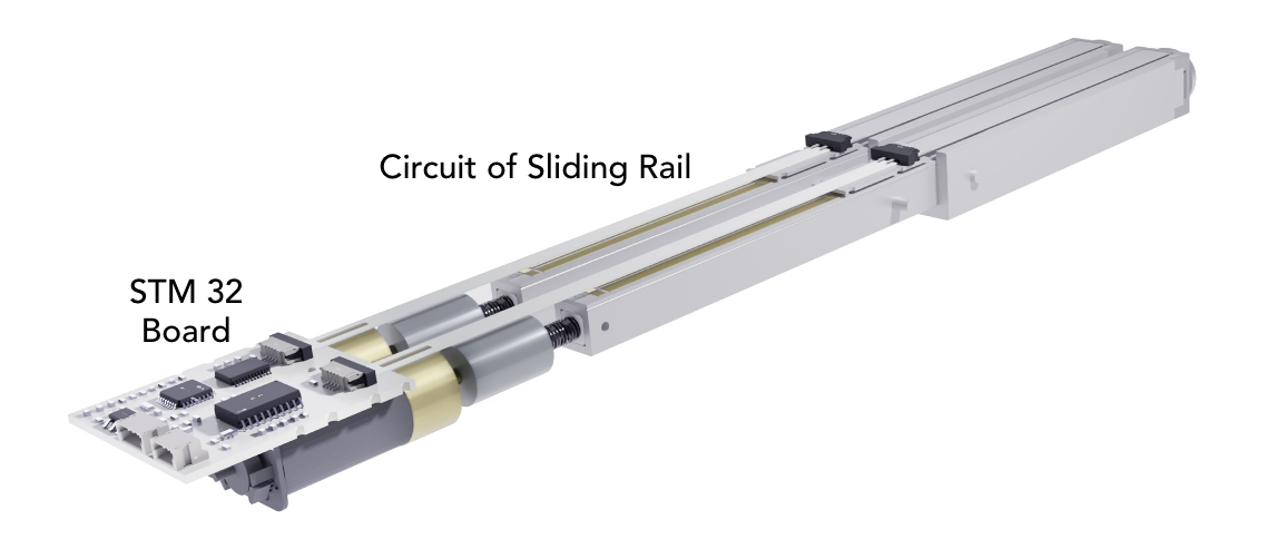
| Component | Description | Link |
|---|---|---|
| Atom Unit | Represents a single element of the 16×16 array. | Atom Unit of ArrayBot |
| Control Board | An STM32 board serving as the main controller. | Custom design |
Since the ArrayBot uses a 16x16 array, and every two atom units form a modular unit, it’s easy to figure out we need 128 modular units in total. Simple math, but a huge number🤯.
Getting over 100 custom circuit boards to work together wasn’t easy. There were plenty of hardware failures—soldering errors, broken components, random short circuits—you name it💥. To make sure I had 100 functional boards, I actually had to manufacture over 150. And let me tell you, soldering 150+ boards was an absolute nightmare😵💫. Easily one of the toughest parts of the whole project!
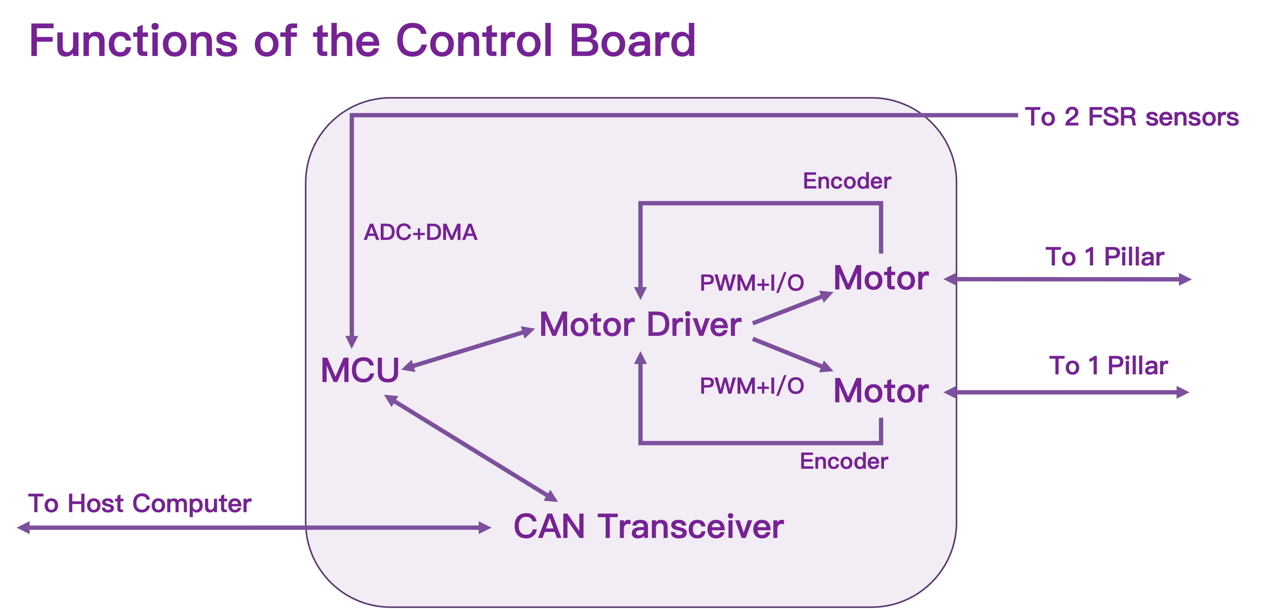
Control Board
The control board manages everything.
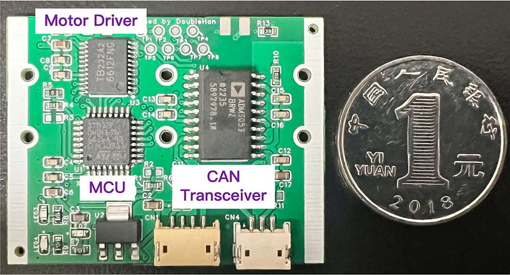
It reads data from the FSR sensors using an Analog-to-Digital Converter (ADC) via Direct Memory Access (DMA). It counts the rising and falling edges of the encoder’s A/B phase rectangular orthogonal pulses, generates PWM signals and basic I/O control signals for the motor driver, and supports the CAN transceiver for communication with the PC.
The actual circuit board is as small as a coin, as shown in the picture below.
I’ve included the schematic design for this control board.
If you’d like to manufacture the same board, you can simply send the Gerber file and pick-and-place file to JLCPCB or PCBWay.